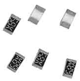
Construction
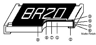
| 1 | Alumina Substrate | 4 | Edge Electrode (NiCr) | 7 | Resistor Layer (NiCr) |
| 2 | Bottom Electrode (Ag) | 5 | Barrier Layer (Ni) | 8 | Overcoat (Epoxy) |
| 3 | Top Electrode (Ag-Pd) | 6 | External Electrode (Sn) | 9 | Marking |
Features
- Tolerance 0.1% to 1%
- Thin film Ni/Cr Resistor
- TCR: 5 to 50 ppm
Applications
- Medical Equipment
- Measurement Instrument
- Communication Devices
- Printer Equipment
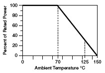
Derating Curve
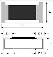
Dimensions (Unit: mm)
| Codes | L | W | T | D1 | D2 |
|---|---|---|---|---|---|
| CR01 | 0.58±0.05 | 0.29±0.05 | 0.23±0.05 | 0.12±0.05 | 0.15±0.05 |
| CR02 | 1.00±0.05 | 0.50±0.05 | 0.30±0.05 | 0.20±0.10 | 0.20±0.10 |
| CR03 | 1.55±0.10 | 0.80±0.10 | 0.45±0.10 | 0.30±0.20 | 0.30±0.20 |
| CR05 | 2.00±0.15 | 1.25±0.15 | 0.55±0.10 | 0.30±0.20 | 0.40±0.25 |
| CR06 | 3.05±0.15 | 1.55±0.15 | 0.55±0.10 | 0.42±0.20 | 0.35±0.25 |
| CR13 | 3.10±0.15 | 2.40±0.15 | 0.55±0.10 | 0.40±0.20 | 0.55±0.25 |
| CR10 | 4.90±0.15 | 2.40±0.15 | 0.55±0.10 | 0.60±0.30 | 0.50±0.25 |
| CR12 | 6.30±0.15 | 3.10±0.15 | 0.55±0.10 | 0.60±0.30 | 0.50±0.25 |
Standard Electrical Specifications
| Item | Power Rating at 70°C |
Operating Temp. Range |
Max. Operating Voltage |
Max. Overload Voltage |
Resistance Tolerance | Resistance Range | TCR PPM/°C |
|---|---|---|---|---|---|---|---|
| Type | |||||||
| CR01 (0201) | 1/32W | -55 ~ +155°C | 15V | 30V | ±0.5% ±1.0% |
49.9Ω~5KΩ | ±25 |
| 49.9Ω~33KΩ | ±50 | ||||||
| CR02 (0402) | 1/16W | -55 ~ +155°C | 25V | 50V | ±0.10% ±0.25% ±0.50% |
10Ω~205KΩ | ±25 ±50 |
| CR03 (0603) | 1/16W | -55 ~ +155°C | 50V | 100V | ±0.10% | 4.7Ω~1MΩ | ±25 ±50 |
| ±0.25% ±0.50% |
2Ω~1MΩ | ||||||
| CR05 (0805) | 1/10W | -55 ~ +155°C | 100V | 200V | ±0.10% | 4.7Ω~2MΩ | ±25 ±50 |
| ±0.25% ±0.50% |
1Ω~2MΩ | ||||||
| CR06 (1206) | 1/8W | -55 ~ +155°C | 150V | 300V | ±0.10% | 4.7Ω~2.5MΩ | ±25 ±50 |
| ±0.25% ±0.50% |
1Ω~2.5MΩ | ||||||
| CR13 (1210) | 1/5W | -55 ~ +155°C | 150V | 300V | ±0.10% | 4.7Ω~2.5MΩ | ±25 ±50 |
| ±0.25% ±0.50% |
1Ω~2.5MΩ | ||||||
| CR10 (2010) | 1/4W | -55 ~ +155°C | 150V | 300V | ±0.10% | 4.7Ω~3MΩ | ±25 ±50 |
| CR12 (2512) | 1/2W | ±0.25% ±0.50% |
1Ω~2.5MΩ |
1.0% & 5.0% tolerances available in all above ranges.
Consult with factory for resistance values & T.C.'s outside of specification shown.
Operating Voltage V = √(PxR)
High Power Rating Electrical Specifications
| Item | Power Rating at 70°C |
Operating Temp. Range |
Max. Operating Voltage |
Max. Overload Voltage |
Resistance Range | TCR PPM/°C |
||
|---|---|---|---|---|---|---|---|---|
| Type | ±0.1% | ±0.25% | ±0.5% | |||||
| CR03 (0603) | 1/10W | -55~+155°C | 75V | 150V | 24.9Ω-15KΩ | ±5 | ||
| 4.7Ω-332KΩ | ±10 | |||||||
| ±15 | ||||||||
| ±25 | ||||||||
| ±50 | ||||||||
| 1/6W | 100V | 150V | 100Ω-332KΩ | ±25 | ||||
| ±50 | ||||||||
| CR05 (0805) | 1/8W | -55~+155°C | 150V | 300V | 24.9Ω-30KΩ | ±5 | ||
| 4.7Ω-511KΩ | ±10 | |||||||
| ±15 | ||||||||
| ±25 | ||||||||
| ±50 | ||||||||
| 4.7Ω-1MΩ | ±15 | |||||||
| ±25 | ||||||||
| ±50 | ||||||||
| 1/4W | 150V | 300V | 100Ω-500KΩ | ±25 | ||||
| ±50 | ||||||||
| CR06 (1206) | 1/4W | -55~+155°C | 200V | 400V | 24.9Ω-50KΩ | ±5 | ||
| 4.7Ω-1MΩ | ±10 | |||||||
| ±15 | ||||||||
| ±25 | ||||||||
| ±50 | ||||||||
| 1/3W | 200V | 400V | 100Ω-1MΩ | ±25 | ||||
| ±50 | ||||||||
| CR13 (1210) | 1/3W | -55~+155°C | 200V | 400V | 24.9Ω-50KΩ | ±5 | ||
| 4.7Ω-1MΩ | ±10 | |||||||
| ±15 | ||||||||
| ±25 | ||||||||
| ±50 | ||||||||
| CR12 (2512) | 3/4W | -55~+155°C | 200V | 400V | 24.9Ω-2KΩ | 4.7Ω-2KΩ | 1Ω-2KΩ | ±15 |
| ±25 | ||||||||
| ±50 | ||||||||
| 1W | 200V | 400V | - | 4.7Ω-100Ω | 1Ω-100Ω | ±25 | ||
| ±50 | ||||||||
Operating Voltage = √(P*R) or Max. operating voltage listed above, whichever is lower.
Overload Voltage = 2.5*√(P*R) or Max. overload voltage listed above, whichever is lower.
Special Electrical Specifications (T.C.s)
| Item | Power Rating at 70°C |
Operating Temp. Range |
Max. Operating Voltage |
Max. Overload Voltage |
Resistance Range | TCR PPM/°C |
||
|---|---|---|---|---|---|---|---|---|
| Type | ±0.1% | ±0.25% | ±0.5% | |||||
| CR02 (0402) | 1/16W | -55~+155°C | 25V | 50V | 49.9Ω-5KΩ | ±5 | ||
| 49.9Ω-100KΩ | ±10 | |||||||
| ±15 | ||||||||
| 49.9Ω-70KΩ | ±15 | |||||||
| CR03 (0603) | 1/16W | -55~+155°C | 50V | 100V | 24.9Ω-15KΩ | ±5 | ||
| 24.9Ω-100KΩ | ±10 | |||||||
| 4.7Ω-332KΩ | ±15 | |||||||
| CR05 (0805) | 1/10W | -55~+155°C | 100V | 200V | 24.9Ω-30KΩ | ±5 | ||
| 24.9Ω-200KΩ | ±10 | |||||||
| 4.7Ω-511KΩ | ±15 | |||||||
| CR06 (1206) | 1/8W | -55~+155°C | 150V | 300V | 24.9Ω-50KΩ | ±5 | ||
| 24.9Ω-500KΩ | ±10 | |||||||
| 4.7Ω-1MΩ | ±15 | |||||||
| CR13 (1210) | 1/5W | -55~+155°C | 150V | 300V | 24.9Ω-50KΩ | ±5 | ||
| 24.9Ω-500KΩ | ±10 | |||||||
| 4.7Ω-1MΩ | ±15 | |||||||
| CR10 (2010) | 1/4W | -55~+155°C | 150V | 300V | 24.9Ω-100KΩ | ±5 | ||
| 24.9Ω-500KΩ | ±10 | |||||||
| 4.7Ω-1MΩ | ±15 | |||||||
| CR12 (2512) | 1/2W | -55~+155°C | 150V | 300V | 24.9Ω-100KΩ | ±5 | ||
| 24.9Ω-500KΩ | ±10 | |||||||
| 4.7Ω-1MΩ | ±15 | |||||||
Operating Voltage = √(P*R) or Max. operating voltage listed above, whichever is lower.
Overload Voltage = 2.5*√(P*R) or Max. overload voltage listed above, whichever is lower.
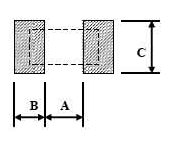
Recommend Land Pattern (Unit: mm)
| Codes | A | B | C |
|---|---|---|---|
| CR12 | 4.90 | 1.60 | 3.10±0.2 |
| CR10 | 3.60 | 1.40 | 2.50±0.2 |
| CR13 | 2.00 | 1.15 | 2.50±0.2 |
| CR06 | 2.00 | 1.15 | 1.70±0.2 |
| CR05 | 1.00 | 1.00 | 1.35±0.2 |
| CR03 | 0.80 | 1.00 | 0.90±0.2 |
| CR02 | 0.50 | 0.50 | 0.60±0.2 |
| CR01 | 0.25 | 0.30 | 0.40±0.2 |
Environmental Characteristics
| Test Item | Specification | Test Method | |
|---|---|---|---|
| Tol. ≤0.05% | Tol.>0.05% | ||
| Temperature Coefficient of Resistance | As Spec | MIL-STD-202F Method 304 +25/-55/+25/+125/+25°C |
|
| Short Time Overload | ΔR±0.05% | ΔR±0.5% | JIS-C-5202-5.5 RCWV'2.5 or Max Overloading Voltage, 5 seconds |
| ΔR±0.5% for high power rating | |||
| Dielectric Withstand Voltage | By type | MIL-STD-202F Method 301 Apply Max Overload Voltage for 1 minute |
|
| Insulation Resistance | >1000MΩ | MIL-STD-202F Method 302 Apply 100Vpc for 1 minute |
|
| Thermal Shock | ΔR±0.05% | ΔR±0.25% | MIL-STD-202F Method 107G -55~+150°C 100 cycles |
| Load Life | ΔR±0.05% | ΔR±0.25% | MIL-STD-202F Method 108A RCWV, 70°C, 1.5 hours ON, 0.5 hours OFF, total 1000~1048hours |
| >7kΩΔR±0.5% | |||
| ΔR±0.5% for high power rating | |||
| Humidity (Steady State) | ΔR±0.05% | ΔR±0.30% | MIL-STD-202F Method 103B 40°C, 90~95%RH, RCWV 1.5 hours ON, 0.5 hours OFF, total 1000~1048 hours |
| ΔR±0.5% for high power rating | |||
| Resistance to Dry Heat | ΔR±0.05% | ΔR±0.20% | JIS-C-5202-7.2 96 hours @ +155°C without load |
| Low Temperature Operation | ΔR±0.05% | ΔR±0.20% | JIS-C-5202-7.1 1 hour, -65°C followed by 45 minutes of RCWV |
| ΔR±0.5% for high power rating | |||
| Bending Strength | ΔR±0.05% | ΔR±0.20% | JIS-C-5202-6.1.4 Bending Amplitude 3mm for 10 seconds |
| Solderability | 95% min coverage | MIL-STD-202F Method 208H 245°C±5°C, 3±0.5(sec) |
|
| Resistance to Soldering Heat | ΔR±0.05% | ΔR±0.20% | MIL-STD-202F Method 210E 260±5°C, 10±1 seconds |
* Storage Temperature: 25±3°C; Humidity < 80%RH
Packaging - Quantity & Reel Specifications (Unit: mm)
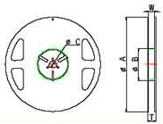
| Codes | ΦA | ΦB | ΦC | W | T | Paper Tape (EA) | Emboss Plastic Tape (EA) |
|---|---|---|---|---|---|---|---|
| CR01 | 178.0 ± 1.0 | 60.0 ± 1.0 | 13.5 ± 0.7 | 9.5 ± 1.0 | 11.5 ± 1.0 | 10,000 | - |
| CR02 | 178.0 ± 1.0 | 60.0 ± 1.0 | 13.5 ± 0.7 | 9.5 ± 1.0 | 11.5 ± 1.0 | 10,000 | - |
| CR03 | 178.0 ± 1.0 | 60.0 ± 1.0 | 13.5 ± 0.7 | 9.5 ± 1.0 | 11.5 ± 1.0 | 5,000 | - |
| CR05 | 178.0 ± 1.0 | 60.0 ± 1.0 | 13.5 ± 0.7 | 9.5 ± 1.0 | 11.5 ± 1.0 | 5,000 | - |
| CR06 | 178.0 ± 1.0 | 60.0 ± 1.0 | 13.5 ± 0.7 | 9.5 ± 1.0 | 11.5 ± 1.0 | 5,000 | - |
| CR13 | 178.0 ± 1.0 | 60.0 ± 1.0 | 13.5 ± 0.7 | 9.5 ± 1.0 | 11.5 ± 1.0 | 5,000 | - |
| CR10 | 178.0 ± 1.0 | 60.0 ± 1.0 | 13.5 ± 0.7 | 9.5 ± 1.0 | 11.5 ± 1.0 | - | 4,000 |
| CR12 | 178.0 ± 1.0 | 60.0 ± 1.0 | 13.5 ± 0.7 | 9.5 ± 1.0 | 11.5 ± 1.0 | - | 4,000 |
Packaging - Paper Tape Specifications (Unit: mm)

| Codes | A | B | W | E | F | P0 | P1 | P2 | ΦD0 | T |
|---|---|---|---|---|---|---|---|---|---|---|
| CR01 | 0.40±0.05 | 0.70±0.05 | 8.00±0.10 | 1.75±0.05 | 3.5±0.05 | 4.00±0.10 | 2.00±0.05 | 2.00±0.05 | 1.55±0.05 | 0.26±0.05 |
| CR02 | 0.70±0.05 | 1.16±0.05 | 8.00±0.10 | 1.75±0.05 | 3.5±0.05 | 4.00±0.10 | 2.00±0.05 | 2.00±0.05 | 1.55±0.05 | 0.40±0.03 |
| CR03 | 1.10±0.05 | 1.90±0.05 | 8.00±0.10 | 1.75±0.05 | 3.5±0.05 | 4.00±0.10 | 4.00±0.10 | 2.00±0.05 | 1.55±0.05 | 0.60±0.03 |
| CR05 | 1.60±0.05 | 2.37±0.05 | 8.00±0.10 | 1.75±0.05 | 3.5±0.05 | 4.00±0.10 | 4.00±0.10 | 2.00±0.05 | 1.55±0.05 | 0.75±0.05 |
| CR06 | 2.00±0.05 | 3.55±0.05 | 8.00±0.10 | 1.75±0.05 | 3.5±0.05 | 4.00±0.10 | 4.00±0.10 | 2.00±0.05 | 1.55±0.05 | 0.75±0.05 |
| CR13 | 2.75±0.05 | 3.40±0.05 | 8.00±0.10 | 1.75±0.05 | 3.5±0.05 | 4.00±0.10 | 4.00±0.10 | 2.00±0.05 | 1.60±0.10 | 0.75±0.05 |
Packaging - Emboss Plastic Tape Specifications (Unit: mm)

| Codes | A | B | W | E | F | P0 | P1 | P2 | ΦD0 | T |
|---|---|---|---|---|---|---|---|---|---|---|
| CR10 | 2.85±0.10 | 5.45±0.10 | 12.0±0.10 | 1.75±0.10 | 5.5±0.05 | 4.00±0.05 | 4.00±0.10 | 2.00±0.05 | 1.50±0.10 | 1.00±0.20 |
| CR12 | 3.40±0.10 | 6.65±0.10 | 12.0±0.10 | 1.75±0.10 | 5.5±0.05 | 4.00±0.05 | 4.00±0.10 | 2.00±0.05 | 1.50±0.10 | 1.00±0.20 |
How To Order
Example: 0603 100Ω 0.5% 50ppm 1/10W Tape

1. Product Type
| Product Type | |
|---|---|
| CR | Thin Film Precision Chip |
2. Dimensions (L x W)
| Codes | Dimensions (LxW) | EIA |
|---|---|---|
| CR01 | 0.58x0.29mm | 0201 |
| CR02 | 1.0x0.50mm | 0402 |
| CR03 | 1.6x0.80mm | 0603 |
| CR05 | 2.0x1.25mm | 0805 |
| CR06 | 3.0x1.50mm | 1206 |
| CR13 | 3.10x2.40mm | 1210 |
| CR10 | 4.90x2.40mm | 2010 |
| CR12 | 6.30x3.10mm | 2512 |
3. Resistance
| Codes | Type |
|---|---|
| 1000 | 100Ω |
| 2201 | 2200Ω |
| 1002 | 10000Ω |
| 4992 | 49900Ω |
| 1003 | 100000Ω |
4. Resistance Tolerance
| Codes | Resistance Tolerance |
|---|---|
| A | ±0.05% |
| B | ±0.1% |
| C | ±0.25% |
| D | ±0.5% |
| F | ±1% |
5. TCR
| Codes | Type |
|---|---|
| S | ±5PPM/°C |
| B | ±10PPM/°C |
| N | ±15PPM/°C |
| C | ±25PPM/°C |
| D | ±50PPM/°C |
6. Power Rating
| Codes | Type |
|---|---|
| Standard | |
| X | 1/10W |
| Y | 1/16W |
| W | 1/8W |
| V | 1/4W |
| O | 1/3W |
| S | 3/4W |
| T | 1W |
7. Packaging
| Code | Type |
|---|---|
| T | Taping Reel |
| B | Bulk |

