|
||||||
 |
|
|||||||||||||||||||||||||||||||||||||||||||||
|
|||||||||||||||||||||||||||||||||||||||||||||
|
||||||||||||||||||||||||||||||||||||||||||||||||||
|
||||||||||||||||||||||||||||||||||||||||||||||||||
 |
 |
| Performance Specifications | |||||||||||||||||
| Characterisitcs | Test Methods | Limits | |||||||||||||||
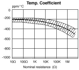
| Temperature coefficient JIS -C -5202 5.2 |
Natural resistance change per temp. degree centigrade
R1: Resistance value at room temperature (t1) R2: Resistance value at room temp. + 100°C (t2) Test pattern: Room temp., Room temp. +100°C |
|
|||||||||||||||
| Dielectric withstanding voltage JIS - C - 5202 5.7 |
Resistors shall be clamped in the trough of a 90° metalic V-block and shall be tested at AC potential respectively specified in the above list for 60 +10 / -0 seconds. |
No evidence of flashover, mechanical damage, arcing or insulation break down. | |||||||||||||||
| Temperature cycling JIS - C - 5202 7.4 |
Resistance change after continuous five cycles for duty cycle specified below:
|
Resistance change rate is ± (1% +0.05 |
|||||||||||||||
| Short-time overload JIS - C - 5202 5.5 |
Permanent resistance change after the application of a potential of 2.5 times RCWV for 5 seconds. | Resistance change rate is ± (1% +0.05 |
|||||||||||||||
| Load life in humidity JIS - C - 5202 7.9 |
Resistance change after 1,000 hours operating at RCWV with duty cycle of 1.5 hours "ON", 0.5 hour "OFF" in a humidity test chamber controlled at 40°C ± 2°C and 90- 95% relative humidity. |
|
|||||||||||||||
| Load life JIS - C - 5202 7.10 |
Permanent resistance change after 1,000 hours operating at RCWV, with duty cycle of 1.5 hours "ON", 0.5 hour "OFF" at 70°C ± 2°C ambient. |
|
|||||||||||||||
| Insulation resistance JIS - C - 5202 5.6 |
Resistors shall be clamped in the trough of a 90° metalic V-block and shall be tested at DC potential respectively specified in the above list for 60 +10 / -0 seconds. |
Insulation resistance is 10,000M |
|||||||||||||||
| Terminal strength JIS - C - 5202 6.1 |
Direct load: Resistance to a 2.5 kg direct load for 10 seconds in the direction of the longitudinal axis of the terminal leads. Twist test: Terminal leads shall be bent through 90° at a point of about 6mm from the body of the resistor and shall be rotated through 360° about the original axis of the bent terminal in alternating direction for a total of 3 rotations. |
No evidence of mechanical damage | |||||||||||||||
| Resistance to soldering heat JIS - C - 5202 6.4 |
Permanent resistance change when leads immersed to 3.2 - 4.8 mm from the body in 350°C ± 10°C solder for 3 ± 0.5 sec. | Resistance change rate is ± (1%+0.05 |
|||||||||||||||
| Solderability JIS - C - 5202 6.5 |
The area covered eith a new, smooth, clean, shiny and continuous surface free from concentrated pinholes. Test temp. of solder: 235°C ± 5°C Dwell time in solder: 3 +0.5 / -0 seconds |
95% coverage min. | |||||||||||||||
| Resistance to solvent JIS - C - 5202 6.9 |
Specimens shall be immersed in a bath of trichroethane completely for 3 minutes with ultrasonic. | No deterioration of protective coatings and markings | |||||||||||||||
|
|||||||||||||||||||||
| TO ORDER PRODUCTS |
| E mail: microohm@mail.com |
| Call Toll Free: 1-800-845-5167 |
| home page | product guide |