| product guide | |||||
|
|||||
|
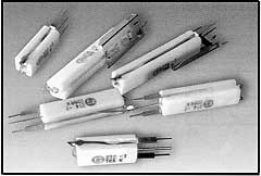
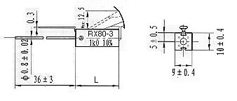
Configuration
|
|||||
 |
 |
||||
|
Technical Specifications
|
||||||
| Type | Rated Power (W) | Resistance Range | Dimensions (mm) | |||
| Min. | Max. | |||||
|
25 °C
|
70 °C
|
10% | 5% |
L
|
||
| RX80-3 | 3.0 | 2.0 | R075 | R15 | 1K5 | 25 ± 1.0 |
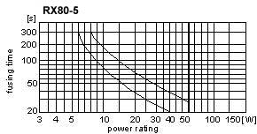
| RX80-5 | 5.5 | 2.5 | R11 | R33 | 3K3 | 38 ± 1.0 |
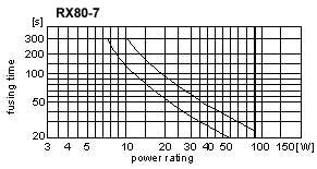
| RX80-7 | 7.0 | 3.5 | R28 | R51 | 4K7 | 50 ± 1.5 |
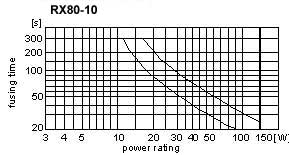
| RX80-10 | 10.0 | 4.5 | R27 | R91 | 8K2 | 75 ± 2.0 |
| Characteristics | |
| Test Condition | Specifications |
| Tolerances | ± 5% (J) ± 10% (K) |
| TCR | -80 ~ + 500 ppm/°C |
| Insulation Voltage | 200V |
| Insulation Resistance | > 104 M |
| Climate category | 55 / 150 / 56 |
| Temperature range | - 55 ~ 150°C |
| Power derating | Ref. Fig. 1 Solder Joint Temperature |
| Failure rate | Approximate to 100 10-9 h-1 / 100 x 10 -9/hour |
| Load life: P70 @ 70 °C, 1000 hrs | |
| Damp heat, steady state 40 °C, 93%RH, 56 days | |
| Climate sequence | |
| Terminal strength | |
| Terminal tensile strength | 50N |
| Solder heat resistance 260°C, 10 sec. | |
| Solderability | IEC68 - 2 - 20 - T |
|
Fig. 1 Solder Joint Temperature
|
|
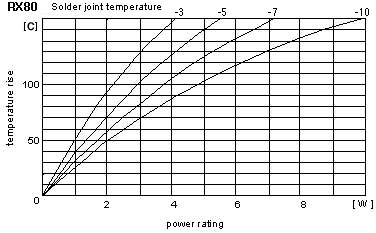 |
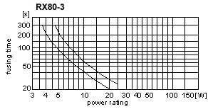
Temperature at solder joint should never exceed 150°C under normal working conditions. Solder joint temperature is defined as sum of ambient temperatue and temperature rise caused by applied load. After fusing, the fusable solder joint can be repaired with regular solder 60 / 40 SN / pb |
| . | |
|
Fig. 2 Blow Characteristics
|
|
 |
 |
 |
 |
|
|||||||||||||||||||||
| home page | product gude | TO ORDER PRODUCTS |
| E mail: microohm@mail.com | ||
| Call Toll Free: 1-800-845-5167 |