

Construction
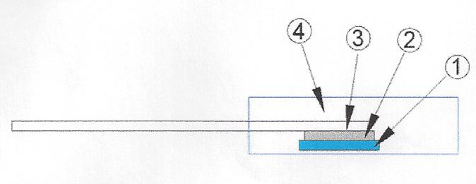
| 1 | Alumina Substrate | 3 | Lead |
| 2 | Resistor Layer | 4 | Molding |
Features
- 20 Watts at 25°:C case temperature heat sink mounted
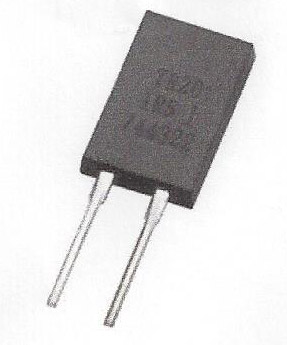
- TO-220 style power package
- Molded case for protection and easy to mount
- Electrically isolated case
- Non-inductive design
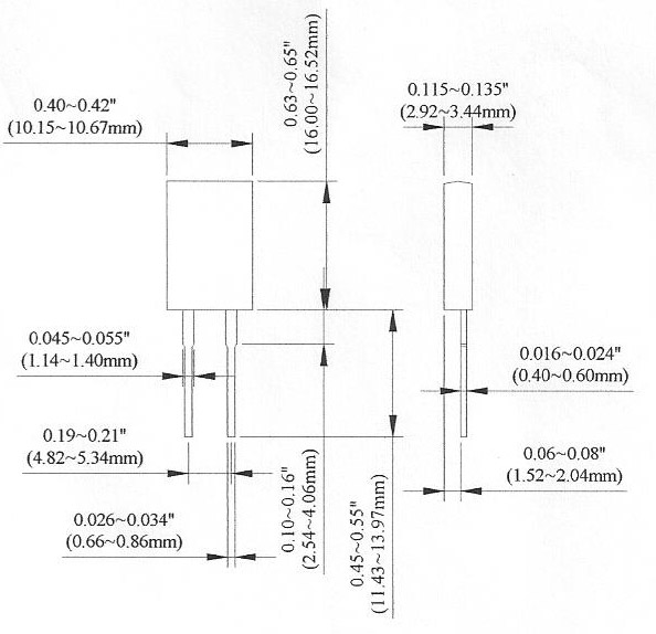
Dimensions Unit:mm
| Type | Weight (g) (1000pcs) |
|---|---|
| TP20 | 1290 |
Applications
- High Speed Switching Power Supplies
- Snubber Circuits
- Load Resistor for Pulse Generators
- Voltage Regulation
- VHF Amplifiers
Electrical Characteristics Specifications
| Item | Resistance Range | TCR (PPM/°C) |
|||
|---|---|---|---|---|---|
| Type | ±0.5% | ±1% | ±5% | ±10% | |
| TP20 | - | - | 0.05Ω-1Ω | No Specified | |
| - | >1Ω-3Ω | ±300 | |||
| - | >3Ω-10Ω | ±100 ±200 |
|||
| >10Ω-10KΩ |
±50 ±100 ±200 |
||||
- Operating Voltage: 350V max.
- Dielectric Strength: 1800VAC
- Insulation Resistance: 10GΩ min.
- Working Temperature Range: -65°C to +150°C
- Resistance Value <1Ω is available
How To Order:
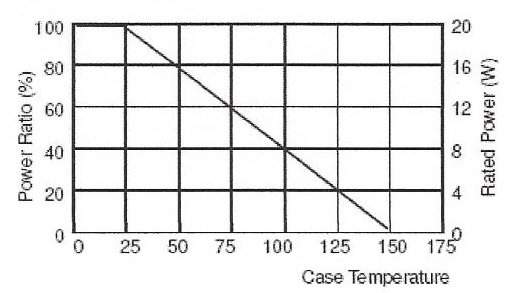
Derating Curve
Part Numbering
TP
- Product Type:
20
- Power
-
- 20: 20 Watts
J
- Resistance Tolerance
-
- D: ±0.5%
- F: ±1%
- J: ±5%
- K: ±10%
B
- Packaging Code
-
- B: Bulk
D
- TCR
(PPM/°C) -
- D: ±50
- E: ±100
- F: ±200
- G: ±300
- -: No Specified
1001
- Resistance
-
- R100: 0.1Ω
- 0100: 10Ω
- 4700: 470Ω
- 1001: 1000Ω
- 1002: 10000Ω
Environmental Characteristics
| Test Item | Requirement | Test Method |
|---|---|---|
| Temperature Coefficient of Resistance (T.C.R.) | As Spec. | Referenced to 25°C, ΔR taken at +105°C |
| Short Time Overload | ΔR±0.3% | 2 times rated power with applied voltage not to exceed 1.5 times Maximum continuous operating voltage for 5 seconds |
| Load Life | ΔR±1% | 2000 hours at rated power |
| Damp Heat with Load | ΔR±0.5% | 40±2°C, 90~95% R.H. Max. working voltage for 1000 hrs with 1.5 hrs "ON" and 0.5 hrs "OFF" |
| Solderability | 90% min. coverage | 245±5°C for 3 seconds |
| Thermal Shock | ΔR±0.3% | -65°C~150°C, 100 cycles |
| Terminal Strength | ΔR±0.2% | (Pull Test) 2.4N |
| Vibration, High Frequency | ΔR±0.2% | 20g peak |
- Lead Material: Tinned Copper
- Without a Heat Sink
- When in Free Air at 25°C, the TP20 is Rated for 3W
- The Case Temperature is to be used for the Definition of the Applied Power Limit
- The Case Temperature Measurement must be made with a Thermocouple Contacting the Center of the Component mounted on the Designed Heat Sink.
- Thermal Grease should be Applied Properly