|
||||
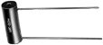
| CONSTRUCTION: | |
| Controlled stress windings are reverse pi wound (non-inductive) on special high temperature epoxy bobbins and terminated using controlled welds. An extensive accelerated aging program provides the ultimate in stabilization. A resilient inner coating and dry air chamber isolate exterior protective epoxy shell from windings to increase moisture protection and stability. Leads are firmly anchored inside bobbin with a high temperature epoxy that assures excellent structural strength. Standard marking includes Trademark, part number, resistance value and resistance tolerance. | |
| FEATURES: | |
| Resistance Tolerances: To ±.005% (25°C) Temperature range: -65°C to 150°C | |
| Temperature coefficients of resistance to 0 ±1PPM/°C | |
| Exceptional resistance stability. | |
| All terminations made of controlled welds. | |
| Fast rise time and minimum phase shift available on selected styles. | |
| Extremely low noise. | |
| Marking impervious to most cleaning agents. | |
| New micro-miniature sizes available. | |
| Exceed the applicable requirements of Mil-R-93. | |
| STANDARD TOLERANCES: | |
| 1%, 0.5%, 0.25%, 0.1%, 0.05%, 0.01% and 0.005% of marked resistance value (calibrated at +25°C ±1°C) Special tolerances are available on request. | |
| STANDARD LEAD MATERIAL: | |
| Tinned Copper | |
| Measurements are made with equipment calibrated to the absolute ohm standard. Since electrical limitations exist in terminating resistance wire, there are minimum tolerance limits applicable to various resistance ranges. These tolerances with corresponding resistance values as shown below. |
| Tolerance (%) | Resistance Value | Tolerance (%) | Resistance Value |
| 0 ± .005 | 1000 |
0 ± .01 | 50 |
| 0 ± .05 | 5 |
0 ± .10 | 1 |
| 0 ± .25 | .05 |
- - | - - |
| Standard Temperature Coefficient of Resistance | |||
| PPM/° C | Resistance | PPM/° C | Resistance |
| 0 ± 10 | 1000 |
0 ± 15 | 10 |
| 0 ± 30 | 1 |
0 ± 90 | less than 1 |
| For resistance values higher than shown please contact our engineering department. | |||
 |
Dimension Shown in Inches. Conversion to M.M. = Inch x 25.4
| M-O P/N | Mil R-93 Equiv. |
Length (L) ±.032 |
Dia. (D) ±.015 |
Lead Awg (d) | Lead Spacing (S) ±.032 |
Mtg. Hole (H) |
Com'l Wattage | Max.DC Voltage | Max Resistance .0006 wire |
| *221 | -- | .490 | .365 | 24 | .390 | .140 | .50 | 300 | 2.5M |
| *211 | -- | .325 | .375 | 24 | .245 | .120 | .50 | 300 | 1.5M |
| *226 | -- | 1.000 | .375 | 20 | .855 | .089 | 1.00 | 600 | 5M |
| 222 | -- | .688 | .420 | 20 | .555 | none | 1.00 | 600 | 3M |
| 236 | -- | 1.125 | .435 | 20 | .960 | none | 1.25 | 600 | 5M |
| *220 | RB17 | 1.000 | .500 | 20 | .845 | .140 | 1.00 | 600 | 10M |
| *228 | RB73 | 2.000 | .500 | 20 | 1.750 | .140 | 2.00 | 1200 | 20M |
| *227 | RB08 | .500 | .550 | 20 | .235 | .140 | .50 | 300 | 1M |
| *224 | RB16 | .612 | .550 | 20 | .475 | .140 | .50 | 300 | 12M |
| *230 | RB18 | 1.250 | .750 | 20 | 1.125 | .140 | 2.00 | 600 | 20M |
| *Items also available with lugs. Order as 6XX. | |||||||||
| For resistance values higher than shown please contact our engineering department. | |||||||||
| Subminiatures | |||||||||
| M-O P/N | Mil R-93 Equiv. |
Length (L) ±.032 |
Dia. (D) ±.015 |
Lead Awg (d) | Lead Spacing (S) ±.032 |
Mtg. Hole (H) |
Com'l Wattage | Max.DC Voltage | Max Resistance .0006 wire |
| 225 | -- | .500 | .160 | 24 | .385 | none | .20 | 200 | 500K |
| *202 | -- | .250 | .312 | 24 | .180 | .089 | .25 | 200 | 500K |
| 243 | -- | .500 | .250 | 22 | .290 | none | .25 | 300 | 300K |
| *Items also available with lugs. Order as 6XX. | |||||||||
| For resistance values higher than shown please contact our engineering department. | |||||||||
| Micro-Miniatures | |||||||||
| M-O P/N | Mil R-93 Equiv. |
Length (L) ±.032 |
Dia. (D) ±.015 |
Lead Awg (d) | Lead Spacing (S) ±.032 |
Mtg. Hole (H) |
Com'l Wattage | Max.DC Voltage | Max Resistance .0006 wire |
| **206 | -- | .200 | .105 | 30 | .100 | none | .30 | 100 | 30K |
| 210 | -- | .250 | .100 | 28 | .200 | none | .05 | 100 | 30K |
| 205 | -- | .165 | .075 | 30 | .150 | none | .04 | 50 | 11K |
| **Silicone coated. | |||||||||
| For resistance values higher than shown please contact our engineering department. | |||||||||
|
||||||||||||||||||||||||||||
| How to Order Micro-Ohm Resistors |
| TO ORDER PRODUCTS |
| E mail: microohm@mail.com |
| Call Toll Free: 1-800-845-5167 |
| home page | product guide | 100 - axial | 400 - printed circuit,cyl. | 400 - printed circuit,rect. |