|
|
 |
 |
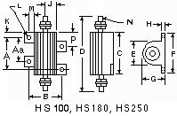
Power Resistor - Series HS
(Heat Sink)
5W to 250W |
|
|
|
| FEATURES: |
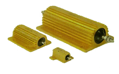
| Aluminum Finned Heat Sink Case |
- Molded Construction |
| Screw Mounts on Chassis |
- Complete Welded Construction |
| Heavy Spade lug type leads |
- High Stability at Conventional Power Ratings |
| ELECTRICAL SPECIFICATIONS: |
| Models: 5, 10, 25 and 50 watts |
- Resistance Range: .05 ohms to 200K ohms |
| Tolerances: .05% to 10% |
- Temperature Coefficient: 20PPM to 90PPM |
| Dielectric Strength: 1000 VAC min. |
- Non-inductive available: add letter N after P/N |
| POWER RANGE: HS resisitor ratings are based on the following (2) requirements: |
| (1) 275°C max. internal hotspot temp. |
(2) 1% max.  R in 1000 hour load life for all models. R in 1000 hour load life for all models. |
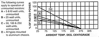
| DERATING: HS resistors have an operating temperature range of -55° to +275°C. Derating is required for reduced chassis mounting area and for high ambient temperature. |
|
|
| Dimension Shown in Inches. Conversion to M.M. = Inch x 25.4 |
M-O
P/N |
MIL-PRF
18546 |
Com'l
Watt |
Max.
Working
Voltage |
Max.
Res. |
A
±.005 |
B
±.005 |
C
±.032 |
D
±.062 |
E
±.015 |
| HS5 |
RE60 |
5 |
160 |
20K |
.444 |
.490 |
.600 |
1.125 |
.334 |
| HS10 |
RE65 |
10 |
265 |
30K |
.562 |
.625 |
.750 |
1.375 |
.438 |
| HS25 |
RE70 |
25 |
550 |
75K |
.719 |
.781 |
1.062 |
1.938 |
.500 |
| HS50 |
RE75 |
50 |
1250 |
200K |
1.563 |
.844 |
1.968 |
2.781 |
.625 |
|
M-O
P/N |
F
±.015 |
G
±.015 |
H
±.010 |
J
±.010 |
K
±.010 |
L
±.005 |
M
±.015 |
N
±.005 |
Mounting
Hole Size |
| HS5 |
.646 |
.317 |
.075 |
.145 |
.078 |
.093 |
.078 |
.050 |
#2 |
| HS10 |
.812 |
.406 |
.100 |
.203 |
.093 |
.093 |
.094 |
.086 |
#2 |
| HS25 |
1.094 |
.563 |
.094 |
.250 |
.171 |
.125 |
.125 |
.086 |
#2 |
| HS50 |
1.156 |
.625 |
.094 |
.281 |
.196 |
.125 |
.125 |
.086 |
#4 |
|
|
|
| 70 to 250 Watt Resistor |
| Chassis mount units are designed for maximum heat dissipation mounting solidly to metal chassis surface for maximum heat transfer. They are outstanding for their high power dissipation with precision tolerances in minimum physical sizes. |
| Electrical Specifications |
| Resistance Range -.05 ohms to 50K ohms |
| Tolerance - 5%, 3%, 1%, .5%, .25%, .1%, .05% |
| Temperature Coefficient - ± 20 to 90 PPM |
| General Specifications |
| Lower hot spot ratings due to exclusive complete encapsulation of element within anodized aluminum body. |
| Welded construction throughout assures long stable load life. |
| Threaded heavy stud terminals |
| Temperature range -> -55°C to + 275°C |
| 5500 VAC minimum dielectric strength |
|
|
|
|
|
|
| DIMENSIONS |
M-O
P/N |
MIL-PRF
18546 |
Com'l
Watts |
Max. Working Voltage |
Max.
Res. |
A
±.01 |
Aa
±.01 |
B
±.01 |
C
±.094 |
D
±.094 |
E
Ref |
| HS70 |
- |
70 |
1400 |
275K |
2.63 |
- |
0.84 |
2.968 |
3.781 |
0.625 |
| HS100 |
RE77 |
100 |
1900 |
50K |
2.75 |
- |
2.25 |
3.500 |
5.478 |
1.800 |
| HS180 |
- |
180 |
2100 |
50K |
2.77 |
- |
2.50 |
3.500 |
5.478 |
2.125 |
| HS250 |
RE80 |
250 |
2300 |
45K |
3.88 |
3.00 |
2.50 |
4.500 |
7.000 |
2.125 |
|
M-O
P/N |
F
±.031 |
G
±.031 |
H
±.016 |
J
Ref. |
K
±.031 |
L
±.01 |
M
Ref. |
N
- |
P
±.01 |
Screw
Size |
| HS70 |
1.156 |
0.625 |
0.094 |
0.281 |
0.196 |
0.125 |
0.125 |
0.09 |
- |
- |
| HS100 |
2.813 |
1.750 |
0.188 |
0.800 |
0.375 |
0.188 |
0.250 |
12/24 |
- |
#8 |
| HS180 |
3.000 |
2.188 |
0.250 |
0.950 |
0.375 |
0.188 |
0.200 |
12/24 |
- |
#8 |
| HS250 |
3.000 |
2.188 |
0.250 |
1.000 |
0.312 |
0.188 |
0.200 |
1/4/20 |
1.180 |
#8 |
|
| DERATING |
|
 |
|
| Power Rating |
| HS resistor curve D shown above is based on mounting to the following heat sink: |
|
HS 5 & 10
|
4" x 6" x 2 .040" thick aluminum chassis (129 sq. in. surface area) |
|
HS 25
|
5" x 7" x 2 .040" thick aluminum chassis (167 sq. in. surface area) |
|
HS 50
|
12" x 12" x .059" thick aluminum panel (291 sq. in. surface area) |
|
HS 100 & 250
|
12" x 12" x .125" thick aluminum panel (294 sq. in. surface area) |
|