| product guide | ||||
|
||||
 |
||||
| FEATURES: | |
| Series R meets or exceeds the electrical, mechanical enviromental and dimensional requirements of Mil R-26 |
|
| .05% to 10% tolerances | All welded construction. |
| Higher temperature silicone or ceramic coating. | |
| MATERIAL: | |
| Core: Ceramic, Steatite or Alumnia depending on size. |
End Caps: Stainless steel |
| Coating: Special high temperature silicone or ceramic depending on end use. | Standard Terminals: Tinned copperweld. Nickel available on request. |
| Resistance Element: Copper, nickel alloy or nickel chrome alloy, depending on resistance value. | |
| ELECTRICAL: | |
| Resistance Tolerance: Available down to ± .01% on certain values and sizes. | |
| Standard Temperature Coefficient of Resistance: | |
| PPM/°C | Resistance |
| 20 | 10 ohms & over |
| 30 | 1 ohm - 10 ohms |
| 90 | Under 1 ohm |
| Dielectric Strength: 500 VAC for models up to & including 1 watt, 1000 volts for all others. | |
| Short Time Overload: 5 seconds at 5 times rated power all models up to and including 3 watt size. 5 seconds at 10 times rated power on all other styles. |
|
| POWER RATINGS: | |
| R series have two power ratings depending on operating temperature and stability requirements. | |
| Characteristics U: | 275°C maximum hotspot temperature |
| .5% Maximum R in 2000 hour load file. | |
| Characterisitc V: | 375°C Maximum hotspot temperature |
| .3% Maximum
|
|
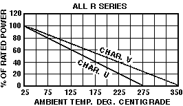
| DERATING: R series have an operating temperature range of -55° to +350°C. They must be derated at high ambient temperature according to the chart at right. |
 |
 |
| M-O P/N | Mil R-26 Equiv. | Length (L) ±.032 |
Dia. (D) ±.032 |
Lead (d) Awg |
Wattage U V |
Max. Working Voltage* U V |
Resistance Ranges (Ohms) |
|||
| .05% .1% .25% | .5% 1% 3% 5% |
|||||||||
| R 1/8 | na | .140 | .065 | 26 | .20 | na | 10 | na | 10-500 | .5-2k |
| R 1/4 | na | .250 | .078 | 24 | .40 | na | 20 | na | 10 - 950 | 1 - 3.4K |
| R 1/2 | na | .312 | .078 | 24 | .75 | na | 29 | na | 10 - 1.3K | 1 - 4K |
| R-1A | RW70 | .406 | .093 | 22 | 1.00 | na | 52 | na | 1- 2.7K | .1 - 10.4K |
| R-1 | na | .531 | .093 | 22 | 1.10 | na | 62 | na | 1- 4.0K | .1 - 15K |
| R2A | na | .430 | .175 | 20 | 2.00 | 2.75 | 130 | 150 | 1- 5K | .01 - 20K |
| R2 1/2 | RW69 | .500 | .210 | 20 | 2.50 | 3.25 | 138 | 157 | 1- 8.6K | .01- 32.3K |
| R2 | na | .531 | .160 | 20 | 3.00 | 3.75 | 135 | 148 | 1 - 5K | .01 - 20K |
| R3A | RW79 | .602 | .210 | 20 | 3.00 | 3.75 | 135 | 148 | 1 - 6.5K | .01- 34.5K |
| R3 | na | .812 | .210 | 20 | 3.25 | 4.75 | 185 | 220 | 1 - 11.4K | .01- 42.1K |
| R4 | na | .625 | .300 | 18 | 4.00 | 5.50 | 210 | 250 | 1 - 12.7K | .01- 47.1K |
| R5 | RW67 / RW74 | .875 | .300 | 18 | 5.00 | 6.50 | 330 | 376 | .5 - 24.5K | .01- 91.0K |
| R7 | na | 1.218 | .375 | 18 | 7.00 | 9.00 | 504 | 576 | .5 - 41.4K | .01- 154K |
| R-10 | RW68 / RW78 | 1.780 | .375 | 18 | 10.00 | 13.00 | 799 | 911 | .5 - 71.3K | .01- 265K |
| *Figured on resistance values using .0008 diameter wire. |
| For non-inductive types add letter N after part number. |
| For ceramic coating add letter C after part number. |